How Anti-Static Flooring Protects Against Damaging Electro-Static Discharges (ESD)
The electronics industry is inherently reliant on state-of-the-art technology, which, while innovative and extremely useful, is also generally sensitive and delicate.
In this guide, we cover the basics of static charges and electrostatic discharges (ESD), and how antistatic floors work to remove the static charges.
|
Table of Contents |
Static electricity discharges, which can easily impair or destroy fragile electronic circuitry, are a common factor that electronic equipment must be protected against. This is exemplified by the fact that some electronic components can be damaged by an electrical discharge of around 300 volts. However, did you know that just one person walking across a floor can generate up to 3,000 volts?
Impact on the Electronics Industry
As a result of this challenge, the electronics industry loses significant amounts of money each year due to damaged goods and broken equipment. To safeguard against this, facilities operating in this market sector should install anti-static flooring solutions as part of the overall ESD Management Scheme.
To ensure that a floor finish will meet the anti-static needs of a site, it is necessary to understand the location's operational activity, how the floor build-up works to eliminate this threat, and the role played by other factors such as testing and personnel clothing.
How is a Static Charge Generated?
Simply put, movement between two surfaces can generate an electric charge, with at least one surface having a high resistance to electric current. The generated electric charge remains until it can be dissipated by an electric current or electrical discharge.
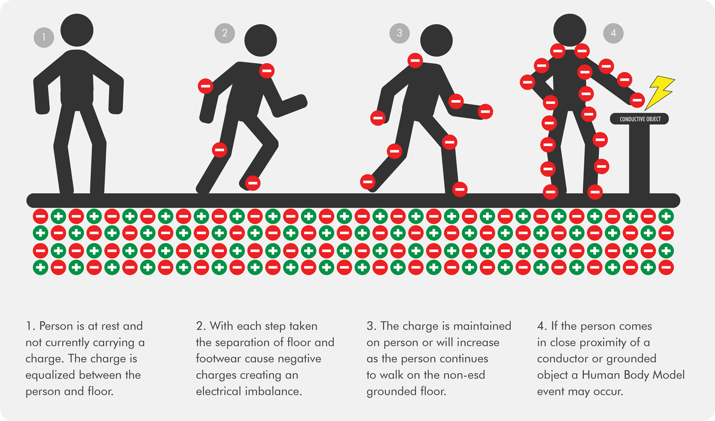
For example, when a person moves across a floor, they can build up a negative charge which increases the more the person moves around.
The process through which a person builds up an electric charge is known as triboelectric charging. This generated electric charge is known as a static charge.
If the stored static charge is significant enough, when a charged object nears a conductive or earthed object, the excess charge will flow between the two objects and neutralise. This phenomenon is an electrostatic discharge, which may produce a visible spark.
If the charged object is a person, the person would experience a mild static shock. However, if the electrostatic discharge passes through a piece of sensitive electronic equipment, it can cause irreversible damage.
While this phenomenon has obvious detrimental implications for the electronics industry, there are also a wide variety of locations where sensitive electronic equipment needs to be protected against electrostatic discharges. To name just a few, the healthcare industry utilises a large number of sensitive electronic life-saving equipment; the aviation industry must ensure that its machinery runs flawlessly in order to keep planes in the air; and any sensitive facility such as a data centre or a cleanroom.
In environments where flammable gases, solvents or dust are present, electrostatic discharges have the potential to be a dangerous ignition source! This eventuality is more common in the munitions and military industries, but it can be a concern in any R&D, production or healthcare environment where flammable elements are present.
Understanding Electrical Resistance
The rate at which an electrical charge is dispersed is controlled by the material’s electrical resistance and is measured in ohms (Ω). The amount of electrical resistance relates directly to the material’s conductivity and ability to move charges out of the area. Essentially, the less resistance there is, the faster the charge can be removed.
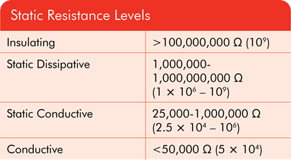
For anti-static purposes, floors are ordered into different categories depending on how quickly electricity can move through them. Materials with the least resistance are defined as conductive, moving to dissipative floors that allow electricity to flow through at a controlled speed and floors at the most resistant end of the spectrum are called insulative.
A good way to think about this is to picture an electrical cable, with a highly conductive metal in the middle which the electricity can move through at a rapid pace, compared to the plastic wiring on the outside which is insulating and through which the electricity cannot move.
How Anti-Static Resin Floors Work
Anti-static floors ground the personnel as they move around the site, preventing damaging levels of static charge from accumulating. This is achieved by constructing a flooring build-up designed to safely transfer the charge from a person to a defined earthing point. In practice, there are several ways that this can be done. We will focus on one of the most popular and effective methods.
The process begins with a resin coating that incorporates specialist conductive materials within the floor. These materials take the charge from people walking across the floor’s surface when their feet come into contact with them and this starts a chain reaction that results in the charge being removed from the area.
Next, the charge hits a conductive primer that has been filled with carbon to ensure a very low level of resistance. Finally, the charge then hits a copper tape buried under the floor coating which is connected to a safe earthing point.
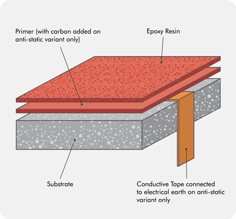
It is important to remember that this is an ideal scenario, and there may be more or fewer steps in practice. It is possible to make a floor that removes static charge without using copper tape, but it will not be as conductive as one that does.
Copper Grids
Copper grids under the primer are an important part of the process, as installing this tape helps to make the flooring system much more conductive.
To recognise the role that the tape plays, it is important to understand its impact on surface resistance. Resistance to earth is measured from a fixed earth point on the floor. The distance from the point of measurement to the earth point has to be specified, if it is not then it should be assumed that it could be at any point on the floor.
This has a major impact on the need for a copper grid, since for materials that are not conductors then the measured resistance will increase when the distance between the measuring points is increased. Thus, the surface resistance will not change across a floor because the electrodes are a fixed distance apart, so the resistance to earth will increase as the electrode is moved further from the earth point.
To combat this, a conductive copper grid increases the size of the earth point and ensures that all parts of the floor are close to the earth point.
The grid must be continuous in order to function, and all grid bays must be connected and/or earthed in some way. In practice, this may cause some complications during the flooring project. One potential complication is that expansion joints might break the flow of the tape. To avoid this, the tape needs to be put down into the joint’s walls and run up the other side to ensure that it is not broken. Alternatively, multiple earthing points should be connected to ensure each bay is fully grounded.
Typically, the copper is applied in 3 m² grids to ensure that everyone moving across the floor is close enough to a line of tape. Any areas of the floor that do not have copper tape nearby risk being much less conductive than the rest of the floor. However, due to the size or shape of the room, it may not always be practical to install these grids.
In these cases, it can be useful to install the copper in a “crows’ feet” formation – the tape spreads out from an earthing point in a number of straight, equally spaced-out lines.
Earthing Requirements
An earthing point is simply an electrical connection that allows any charge that has been transferred to the floor to safely escape to earth. Without an earth, the floor cannot be considered anti-static because any charge that enters it will simply accumulate in the floor.
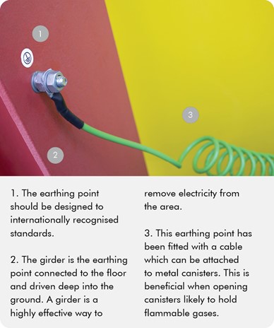
In practice, the typical method of creating a reliable grounding point is to connect to the facility’s existing earthing system.
One earthing point per 200 m² should be sufficient in most cases, but the exact requirements should be specified by an electrical engineer to ensure that the resistance or resistance to earth measurements are appropriate for the task at hand.

Clothing
It is critical that personnel on site wear appropriate clothing to increase the likelihood that any charge built up within a person will be safely grounded.
In some facilities, employees wear wrist straps that are directly connected to grounding points in order to remove charges as quickly as possible. However, while effective, this is not always a practical approach because the straps can be very restrictive for the person wearing them.
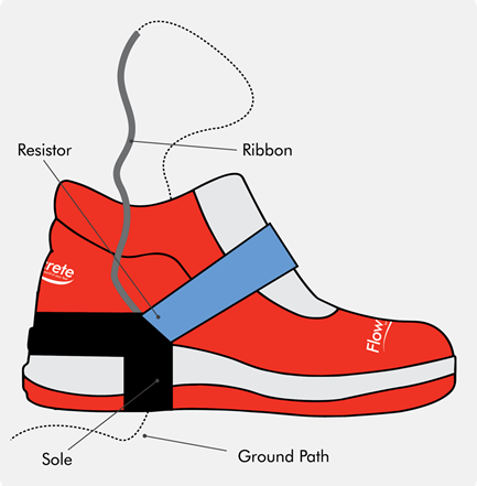
To get the most out of an anti-static floor finish, anyone walking across its surface should be wearing special electro-static dissipative shoes. Without these specialised shoes, the static charge cannot be reliably grounded.
Anti-slip Surfaces
Depending on the nature of the facility’s operations, the antistatic flooring may also need to meet anti-slip requirements to safeguard against slip hazards. Specialised antistatic floor coatings with a textured profile would create safe, anti-slip surfaces for these specific work environments, protecting the users’ wellbeing and safety.
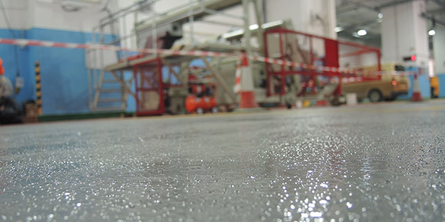 Flowcrete's Flowcoat ESD (Antislip): Antislip antistatic epoxy flooring
The Difference Between Conductive and Dissipative Floors
The term “anti-static flooring” is frequently used as a generalisation for both electro-static dissipative (ESD) and electro-static conductive (ESC) floors. As previously stated, the proper definition is dependent on the conductivity of the floor, with conductive being any floor that has a resistance less than 1.0 × 10⁶ ohms (1 million ohms), and dissipative being any floor that has a resistance between 1.0 × 10⁶ and 1.0 × 10⁹ ohms.
This is demonstrated by the fact that many resin flooring coatings can be either conductive or dissipative depending on how they are applied.
To put it simply, the greater the risk of danger from a spark or electrical discharge (shock), the more conductive the floor needs to be.
This categorisation into static conductive and static dissipative is especially useful for electronics areas where there is a risk of mains shock from hand tools.
Test Methods
There are numerous methods for measuring electrical resistance, and each method can produce different results for the same material, so it is critical to understand the specifics of the test method. The main distinction is the type of test, which can test for surface resistance or earth resistance.
The standard BS EN 61340-5-1 includes a method for determining the resistance of a floor, which has become a popular choice in many countries. The standard details point-to-point conductivity testing using a meter to gauge the amount of resistance between two fixed points on the floor. The outcome of this test will determine whether the floor can be categorised as conductive, dissipative or insulative.
When testing the floor, it is best to move the contact points around to ensure that a footprint sized space has been checked, as this is the contact size that needs to be covered to ensure that any charge held by a person is transferred into the floor.
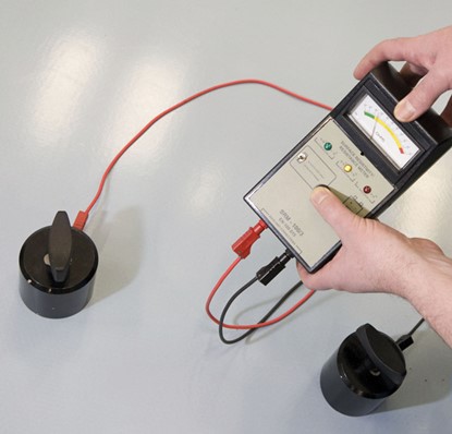
In addition, it is advisable to check after each stage of the flooring project. This is because there may be failures beneath the floor coating that will go undetected if the test is only performed at the end. Ideally, tests should be performed after each stage, especially after the copper grid has been applied, and then again after the primer has been laid down.
Flowcrete Case Studies: Antistatic Flooring
Antistatic floors are specifically designed for use in cleanrooms and manufacturing environments where sensitive electronics, components, gases, solvents or even explosives are handled. Check out Flowcrete's antistatic flooring case studies around the Asia Pacific region, where Flowcrete antistatic flooring systems are used to meet the specific resistance requirements of the facility.
Here are a few selected case studies from around the region:
- Automotive manufacturer, Malaysia
- Electronics components manufacturer, Malaysia
- Toshiba Medical Systems, Malaysia
- Food & beverage production manufacturer, Indonesia
- Macau Polytechnic University, Macau
Further recommendations and advice are available from our network of regional technical and sales representatives.
This guide has been produced to provide an overview of when anti-static flooring is required and how it works.


